
Quality assurance in cable and conductor manufacturing relies on exact measurement protocols, robust physical verification, and predictable electrical characteristics. Modern cable production operates at high throughput speeds, where continuous insulation defects, metallic inclusions, or wall-thickness variations can jeopardize an entire operational infrastructure. Selecting the correct wire testing equipment ensures that every lot leaving the production facility adheres strictly to global electrical and mechanical standards.
Evaluations must extend beyond basic continuity checks. Complete physical characterization requires measuring tensile strength, elongation limits, insulation resistance, micro-ohm conductor resistance, and high-voltage dielectric breakdown capabilities. Comprehensive quality frameworks design diagnostic modules specifically to address these overlapping physical and electrical stress vectors, supporting rigorous quality controls across global industrial supply chains.
Fundamental Mechanics and Electrical Parameters in Wire Evaluation
Physical characterization of conductor materials begins with understanding mechanical deformation under load. When dynamic loads are applied during installation or active service, copper and aluminum conductors experience structural tension. Quantitative assessment requires analyzing tensile yield strength and ultimate elongation before physical separation occurs. Test systems utilize precise load cells paired with optical or contact extensometers to plot stress-strain curves with high repeat accuracy.
Electrical verification requires equal precision. Measuring low resistance across fine wire gauges demands a four-terminal Kelvin architecture to eliminate contact resistance errors. Insulation layers must undergo high-voltage direct current (DC) or alternating current (AC) testing to evaluate dielectric withstand properties. High potential testing identifies localized dielectric weaknesses, pinholes, and void structures embedded within extruded polymeric outer sheaths.
Tensile and Mechanical Property Verification
Conductor draw lines subject metallic rods to severe mechanical reduction, which alters the grain structure of the material. Mechanical evaluation quantifies the ductile properties restored through process annealing. Standardized test procedures pull specimens at controlled crosshead speeds until rupture happens. Key recorded values include:
Yield Strength: The stress point where elastic deformation shifts permanently to plastic deformation.
Tensile Peak Force: The maximum load capacity measured before material necking occurs.
Percentage Elongation: The total length increase relative to original gauge length, confirming material ductility.
Flexural Fatigue Life: Continuous reverse bending cycles designed to simulate long-term dynamic movement.
Dielectric Performance and Insulation Diagnostics
Insulation integrity governs operational safety. Polyethylene, polyvinyl chloride (PVC), and cross-linked fluoropolymer materials require uniform dielectric properties along the entire spool length. Deploying automated wire testing equipment allows quality teams to capture micro-second spark discharge events right at the extrusion line, flagging structural insulation voids before the product reaches spooling stages.
Off-line laboratory verification supplements line monitoring by measuring volume resistivity and surface leakage currents under temperature-controlled environments. These high-precision tests confirm that outer jacket formulations maintain structural resistance when subjected to environmental stressors such as elevated temperatures, humidity, and chemical exposure.
Core Architecture of Industrial Cable Verification Systems
Industrial testing hardware incorporates mechanical load frameworks, high-voltage signal generators, and digital signal processors. High-frequency sinusoidal or high-voltage DC spark testers continuously monitor moving wire stock. The output terminal delivers precise potential differences to an electrode unit—often a bead chain or conductive brush arrangement—through which the insulated wire passes.
When an insulation fault passes through the electrode chamber, the local breakdown creates a transient voltage dip. Internal counter circuits instantly log the discharge event, signaling cutting or marking units without stopping continuous wire movement. High-speed signal acquisition ensures that even high-speed production lines running at several hundred meters per minute record every instance of insulation compromise.
Micro-ohmmeter systems focus on conductor cross-section uniformity. Utilizing low-noise constant current sources alongside precision voltage measurements, these instruments determine conductor resistance down to fractional micro-ohms. Because metallic conductivity varies directly with ambient temperature, advanced instrumentation incorporates real-time thermal compensation sensors, converting output raw values to standardized 20°C equivalents based on copper or aluminum temperature coefficients.
As a premier test equipment supplier in China, HAOEN engages in the comprehensive design and manufacturing of high-grade testing systems. The product scope encompasses environmental test equipment, reliability mechanical test equipment, paper and packaging test equipment, as well as rubber and plastic test equipment, providing complete industrial testing platforms across multiple production sectors.
Selection Criteria for High-Precision Wire Testing Equipment
Selecting appropriate equipment requires matching the structural parameters of the specimen against instrument sensor precision and measurement throughput. Laboratories and production plants evaluate hardware based on measurement accuracy, repeatability, calibration traceability, and structural durability under continuous operating cycles.
System selection hinges on four core criteria:
Measurement Sensitivity: Precision levels must match tight manufacturing tolerances, particularly for ultra-fine magnet wire or aerospace-grade sub-millimeter conductors.
Throughput Speed: Diagnostic equipment must match active extrusion line velocities without introducing artificial measurement noise or physical abrasion.
Environmental Stability: Test chambers must maintain steady thermal and humidity environments during accelerated thermal aging or environmental stress cracking cycles.
Data Protocol Integration: Standard industrial communication protocols like Ethernet/IP or MODBUS permit immediate integration into plant-wide Manufacturing Execution Systems (MES).
Instruments developed by HAOEN integrate precision sensing hardware with open industrial software architectures, simplifying factory-floor deployment and data aggregation. Evaluating specialized wire testing equipment for factory installation involves reviewing calibration stability metrics to ensure long-term, drift-free measurement cycles across multiple shifts.
Industry-Specific Application Scenarios
Different application environments place distinct demands on conductor assemblies. Automotive harness production prioritizes mechanical crimp integrity and resistance to ambient vibrational stress. Aerospace installations demand lightweight, thin-wall insulation capabilities capable of withstanding extreme thermal fluctuations and low atmospheric pressures without electrical arc tracking.
Industrial automation cables require exceptional dynamic flexing endurance. Continuous-flex motion cables mounted inside cable carriers undergo millions of bending cycles. Automated test rigs replicate these precise physical stress patterns in continuous-motion testing stations, assessing internal conductor strands for micro-fractures before complete line breakage occurs.
Automotive Wiring Harness Assemblies
Automotive electrical architectures rely heavily on crimped connections joining multi-strand copper wires to stamped metallic terminals. Mechanical crimp pull testing evaluates the mechanical lock between terminal wings and conductor cores. Pull-test hardware measures the exact peak force required to pull the conductor out of the terminal barrel, confirming that cold-weld crimp compaction limits meet structural specifications.
Concurrently, automated multi-pin harness testers inspect multi-circuit assemblies for cross-wiring, short circuits, and localized contact resistance. High-voltage DC isolation tests verify that adjacent pins within high-density connectors maintain structural electrical separation.
Aerospace Wire and Cable Systems
Aerospace platforms use specialized fluoropolymer insulation such as PTFE and ETFE to reduce weight while preserving chemical and flame resistance. High-altitude environments increase electrical breakdown tendencies due to lower air density. Specialized high-pot diagnostic units test assemblies under partial vacuum condition simulations, verifying that insulation matrices resist corona discharge phenomenon under elevated operational voltages.
Industrial Motion and Continuous-Flex Cables
Industrial robotics systems subject cables to combined torsional, bending, and tensile stresses. Cable designs utilize fine-wire stranding and specialized short-pitch braiding to resist mechanical fatigue. Test equipment continuously flexes samples across specific bend radii while measuring real-time electrical resistance across every inner conductor channel. Any intermittent resistance spike signals internal strand breakage, defining the operational fatigue limits of the cable layout.
Addressing Structural Defects and Signal Degradation in Cable Production
Conductor cross-section non-uniformity, insulation wall eccentricity, and internal micro-voids represent significant failure modes in cable manufacturing. Eccentricity—where the metallic conductor sits off-center within the insulation material—creates localized thin spots along the outer sheath. These thin walls break down prematurely under high electrical potential stresses.
Continuous inline non-contact measurement devices, including multi-axis laser gauges and electromagnetic inductive sensors, track outer diameter and center offset continuously. Integrating wire testing equipment directly into line control feedback loops enables real-time physical adjustment of extrusion crossheads, eliminating off-center material waste before entire reels are affected.
Signal attenuation and characteristic impedance variations degrade high-frequency data cables like CAT6/7/8 ethernet or high-speed automotive data lines. Specialized high-frequency network analyzer interfaces evaluate structural return loss, near-end crosstalk (NEXT), and phase skew across broadband frequency spectrums, ensuring physical construction meets tight high-speed data transmission standards.
Integrating Compliance Standards into Operational Environments
Global wire and cable manufacturing operates under strict standardized frameworks established by organizations such as ASTM International, the International Electrotechnical Commission (IEC), Underwriters Laboratories (UL), and the International Organization for Standardization (ISO). Compliance requires precise alignment between test parameters and published test methods.
Primary standards controlling physical and electrical test methods include:
IEC 60228: Defines standard cross-sectional areas and electrical resistance requirements for insulated cable conductors.
ASTM B193: Outlines the standard test method for measuring the electrical resistivity of metallic conductor materials.
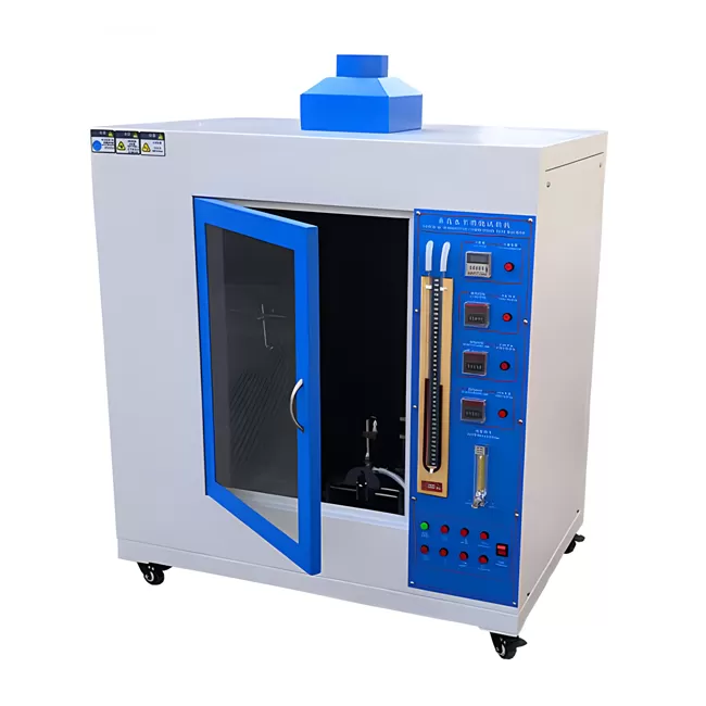
UL 1581: Specifies testing details for electrical wires, cables, and flexible cords, including vertical flame and tension protocols.
ISO 6722: Specifies dimensional, physical, and electrical test requirements for 60 V and 600 V road vehicle cables.
Through long-standing engineering research and manufacturing expertise, industrial testing systems ensure that laboratory measurement data collected on local plant floors matches metrics recorded by third-party certification bodies globally.
Frequently Asked Questions
Q1: What parameters determine the choice between inline dry spark testing and offline water bath voltage immersion testing?
A1: Inline dry spark testing operates continuously during the extrusion process, providing instant detection of pinholes and structural sheath failures at high linear speeds without wetting the product. Offline water bath immersion testing provides complete, uniform dielectric stress across the entire cable length under static conditions, making it suitable for final qualification testing of completed batch spools according to specific standards like IEC 60502.
Q2: How does dynamic temperature compensation function during low-resistance conductor measurements?
A2: Copper and aluminum exhibit positive temperature coefficients, meaning electrical resistance rises as temperature increases. Advanced micro-ohmmeters utilize built-in temperature probes to measure ambient or conductor surface temperatures directly. Internal microprocessors apply the specific material thermal coefficient formula to normalize raw resistance readings instantly to a standardized 20°C reference baseline.
Q3: Why is continuous crimp force monitoring used alongside destructive pull testing in terminal harness production?
A3: Destructive pull testing evaluates mechanical strength on a sampling basis, destroying the sampled terminal in the process. Continuous crimp force monitoring works in real time on automatic termination presses by measuring the compression force profile during every single press stroke. This non-destructive process detects missing wire strands, improper strip lengths, or incorrect crimp height on 100% of manufactured terminations.
Q4: How do high-voltage DC spark testers differ from high-frequency AC spark testers in production environments?
A4: High-voltage DC spark testers apply a continuous static potential, generating lower capacitive current load on thick insulation walls, making them suited for large power cable lines. High-frequency AC spark testers utilize elevated frequencies to create continuous arc paths across thin insulation layers at higher line speeds while using smaller electrode chamber lengths, ideal for high-speed building wire or communication cable lines.
Q5: What structural features prevent cable slippage during mechanical tensile testing of smooth polymer-sheathed wires?
A5: Flexible or smooth outer sheaths can slip out of standard flat mechanical jaws during high-load tensile testing, introducing measurement error. To prevent slippage, test configurations use specialized pneumatic side-action grips with serrated faces or capstan-style roller grips. Capstan grips wrap the wire specimen around a curved drum, distributing clamping friction gradually and preventing premature specimen failure right at the jaw face.
Partner with HAOEN for Advanced Testing Solutions
Achieving consistent product quality requires test equipment built around verified physical principles and dependable measurement hardware. Processing plants require reliable diagnostic infrastructure to maintain tight manufacturing tolerances, control material costs, and ensure absolute compliance with international standards.
Engineering teams planning to update operational testing capabilities, integrate automated inline diagnostics, or re-calibrate laboratory verification facilities are invited to contact HAOEN directly. Submit your commercial inquiries to receive customized wire testing equipment specifications, technical proposals, and detailed system integration options tailored to your precise manufacturing requirements.